
Overhead Line (OHL) personnel safety
Achieving the highest safety standard for OHL personnel
Ensuring access to electricity is crucially important for every country in the world. Whilst local generation is increasingly more available as solar panels are adopted with greater frequency it remains true that electricity grids are dependent on transmission lines. The workers who construct and maintain vital power transmission infrastructure have a difficult job, and one that all too often exposes them to significant health and safety hazards. Until now there have been insufficient methods of controlling that risk to a tolerable level, however now the safety of all overhead transmission line personnel can be protected from the threats of electricity. As such there is no reason or justification for any utility to expose their staff to unnecessary risk.
The above 3D model is an example of our methods for achieving the highest safety standard. Please feel free to interact with the model; you should be able to zoom and rotate in each axis. You may wish to expand the 3D model to fullscreen mode and stop it from rotating.
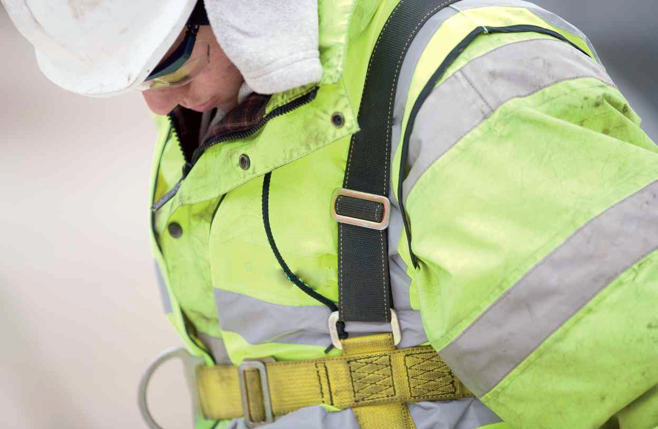
Putting the person back into personnel: The need for personal protective earthing (grounding)
Earthing is an integral part of worker safety both permanent and temporary earthing. As such achieving effective permanent structure earthing is essential, and it must not be subject to the types of in-life deterioration widely noted in metallic-type systems. Furthermore, the temporary earthing systems that engineers will rely on have to ensure safety.
Much of the problem centres on a lack of understanding about what effective earthing is and how it works at both management and operative level. Improved knowledge achieves a double positive of ensuring effective systems are in place, and enabling line operatives to identify any problems that may arise during the course of their work. Ultimately this proactive approach will always achieve a greater level of safety and be significantly more cost efficient.
Following this path will result in a safer work environment for operatives: it saves lives, it’s that simple. Furthermore it will prevent potentially life threatening or life changing injuries. All operatives have the right to expect to get home safely at the end of the day.
Behaviours commonly identified throughout the global power transmission sector
When it comes to opportunities to improve the following points are encountered in almost every power transmission utility in the world:
- Outdated standards and specifications.
- Lack of leadership committed to improve safety performance.
- Insufficient personal protective earthing products.
- Ineffective personal and structural protective earthing methodologies.
- Non-comprehensive equipotential bonding (EPZ) scope.
- Lack of consideration for all potential incidents of touch, step and reach voltages.
- Insufficient or absent site earthing plan.
- Lack of consideration or verification of the overall achieved impedence of earthing and bonding configuration.
- Too narrow a scope of opportunities to improve safety performance.
Temporary Protective Earthing (Grounding): TPE / TPG
- Temporary protective earthing (grounding) [TPEs / TPGs] must be properly designed and sized to carry the maximum available fault current for the required clearing time in the event of inadvertent energisation.
- Temporary protective earthing (grounding) [TPEs / TPGs] must be able to withstand the magnitude and duration of the fault in terms of both thermal and mechanical energy delivered.
- Temporary protective earthing (grounding) [TPEs / TPGs] must be installed to limit worksite exposure voltage (differences in electrical potential) to a safe limit.
- Correct and effective earthing / grounding equipment must be used in conjunction with proper work practices to protect the worker against exposure to hazardous voltage levels under fault conditions.
- TPEs / TPGs must also protect workers from other voltage sources such as electromagnetic induction, capacitive coupling and static voltages.
How we have improved the situation
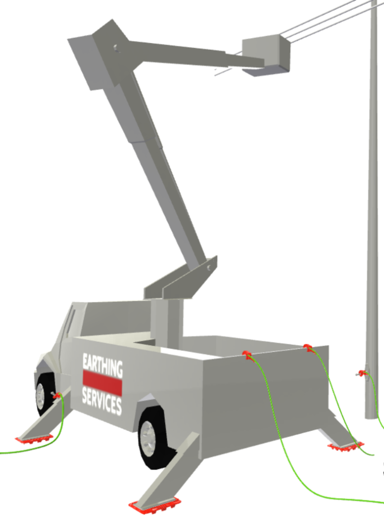
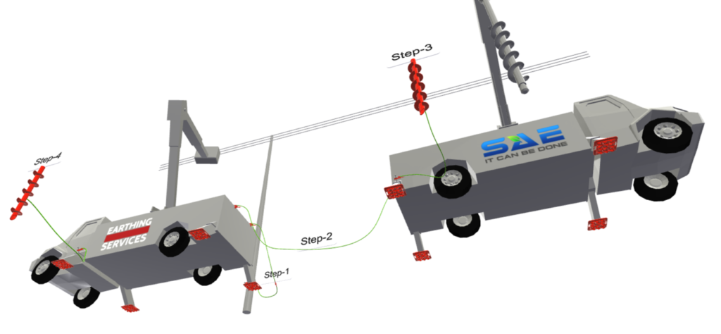
You will note the bonding arrangement includes both vehicles, which are themselves supported by their own earthing provisions through the conductive outrigger stabilisers and the Power Screws (shown in red for clarity).
This process of interconnection results in a plurality of parrallel conductive paths being established over a wider discharge area, and the effect of this is to dramatically reduce the resistance to earth providing enhanced protection in the event of inadvertent energisation.
Furthermore the bonding cables provide superior conductivity and stability of connection.
Can I just apply the configuration with any products?
Applying the design principles using any product on the market may elevate personnel safety above the significant hazards they currently face, however some of the most commonly used and widely available products have been tested demonstrating frightening performance failures. As we explored earlier, temporary protective earthing (grounding) [TPEs / TPGs] must be able to withstand the magnitude and duration of the fault in terms of both thermal and mechanical energy delivered.
Let’s see the evidence.
Bonding cables: DC resistance or AC impedance?
Most calculations are provided based upon the DC resistance of the copper cable. The way a cable is usually sized and selected is based upon the size a simple application of Ohms law.
This video demonstrates the difference between DC resistance and AC impedance.
The use of longer conductors has implications. During the fault this 6m conductor forms a circular arc, which increases the AC impedance during the fault.
Work site exposure voltage is the voltage between one end of the cable and the other. Whilst the DC resistance calculation of the voltage drop is nothing more than the current muplitplied by the resistance of the cable. The impedance component is the voltage being formed across the cable, not the DC resistance as has been historically considered.
As such the circular arc is formed due to the electromagnetic forces involved during the fault event. This is referenced as “loop impedance”.
Guidelines for the installation of bonding cables is to keep them as short as possible, not because of the DC resistance, but to prevent the possibility of slack bonds forming the circular arc, and consequently increasing impedance.
It is a fairly reliable mindset to adopt that every 1.5m of cable represents an additional 50V of worker exposure in the event of a fault resultant of inadvertent energisation. As such keeping those equipotential bonds as short as possible is vital.
Bonding clamp comparison
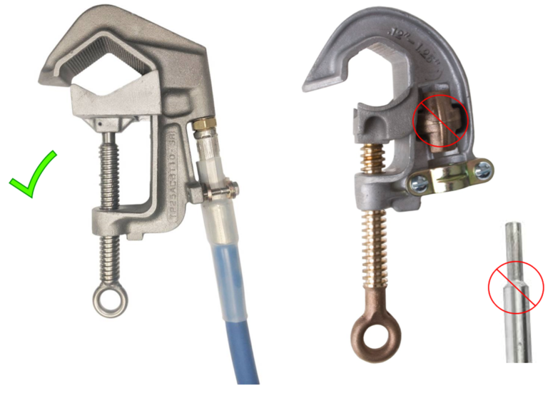
These are two clamps. Not dissimilar in appearance, but differences in performance is significant. Starting with the clamp on the right we see the sort of clamp (plug-style clamp) in active use on numerous work sites; if your projects use this type then please pay attention, because this is especially important for you. This type of clamp features a ferral with a smooth port, or rod which slides into the area circled, which gets clamped down with a nut on the back.
Extensive product testing, on-site performance, and incident investigation concludes that when the mechanical energy involved in some of the higher faults potentially encountered on line work is exerted the smooth ferral fails consequent of repeated force in removing that ferral.
Now if we look to the picture on the left we see a much safer and robust mechanical clamp, here are some of its key features:
- Instead of a relying on a slip-joint connection seen in the smooth ferral this clamp has a threaded port for interconnection resulting in a far more secure connection, and no weakening of the metallic components from repeated use.
- The use of stainless steel prevents the eye-screw from binding during the installation or removal process. This is an important consideration because safety audits frequently identify deficiencies in the application of personal protective earthing / grounding (PPE / PPG) measures due to eye-screws binding prior to effective connections being achieved.
- Serrated jaws of the clamp on the left, which contribute to ensuring the connections remain secure in the event of induction.
- The ferral being crimped for over 50mm (using a radial machine).
- The shroud crimped around the jacket for strength, strain relief and covering the point of connection to prevent moisture ingress.
- The heat shrink providing an extra layer of protection.
All these attributes result in a superior product offering enhanced protection for line workers.
Parallel earth / ground bonding
On occasion workers will install a number of parallel earth / ground bonds. This sort of installation behaviour is often observed when the potential fault current will exceed the maximum rating for a single cable, so the secondary or even tertiary cables are attempts to achieve an acceptable level of personal safety. Unfortunately these best efforts can sometimes result in further exposure to hazards.
This short clip demonstrates the test of double earth / ground bonds installed in parallel 75mm apart and what can happen in the event of inadvertant energisation. During the fault we can observe rotation, the looping action noted in the single bond clip seen previously, contraction of the cable ends and the cable sheath (jacket) separating from the copper conductor beneath as the heat increases.
When you consider that this clip is played in slow motion the real-time version clarifies that any worker in proximity to those bonds during a fault event may suffer injury from that dramatic mechanical reaction.
In this clip we see parallel bonds installed 150mm apart, so only a little further apart than in the previous clip (75mm separation); the consequence is dramatic mechanical failure in five cycles.
To clarify this is the same type of equipment with the same fault level, the only difference in specification of the test was the slight adjustment to the parallel spacing of the earth / ground bonds.
This iteration of testing adopted the same fault level, and same equipment types as the previous examples, however on this testing the variant was moving the conductor spacing from 150mm to 300mm.
The consequence of this adjustment was immediate mechanical failure, occuring within a single cycle. All of the equipment was damaged, and had an operative been within the vicinity their safety would be threatened.
If a utility permits parallel earth / ground bonding then the cable assemblies must be installed as closely together as possible (not exceeding 75mm of spacing) and using a bond clamp of the type shown on the left above.
Installing and removing earthing / grounding bonds is a significant health and safety issue and has resulted in numerous deaths and life changing injuries. Common factors of these sorts of incidents include:
- Not following prescribed workflow
- Not wearing appropriate Personal Protective Equipment (PPE)
- Not using appropriate tools
- Cables being obstructive and so clamps being loosened and relocated without abiding by prescribed connection distances
- Putting earthing /grounding bonds on energised lines
The earthing / grounding of a line seems to result in complacency evidenced in so many of these factors, but so is a lack of understanding of the hazards and insufficient Personal Protective Earthing products. Many of these types of incidents are consequent of electromagnetic inductance, whereby there may be a path to earth / ground through the earthing / grounding bonding arrangement, but that there is a proximity issue. Furthermore the relocation of the equipotential bonds as a matter of expediency or convenience under the presumption that the threat to life is controlled simply by those protective measures being there; the purpose and function of the bond is lost and it is seemingly serving as a child’s safety blanket. This “safety blanket” mentality represents a double harm, after all not only is the threat to safety not being effectively managed, the presumption that it is results in careless behaviour that otherwise would not manifest if the product was not there.
This reinforces the importance of the concept that we keep revisiting:
Get the correct products, in the correct place, in the correct configuration, evidenced by testing using the correct instrument in the correct way, for the whole duration of the works.
Safety is too important to take shortcuts or become complacent because it is the difference between a worker getting home or not.
Spooling cable is easily the most convenient way to transport it, but the convenience of it can result in poor work behaviours that can have drastic consequences.
This video shows an incident demonstrating the impact that leaving wire coiled or spooled can have in the event of inadvertant energisation. This sort of static earth / temporary earth is often used to connect a truck to a structure, or other element benefitting from a permanent earth / ground; it results in an equipotentialised zone, which is important in the event that the truck were to become live. Most prescribed working methods stipulate that these spools are uncoiled in their entirety, and yet all too often this does not happen and operatives only unspool the requisite amount to achieve the connection, play the clip and see what happens.
The spooled cable has high impedance, furthermore the plurality of looped cables essentially forms a solenoid. As high current travels through a wound insulated conductor it exerts significant mechanical forces upon it. In this instance not only could the exploding spool cause injury, whatever protection it was intended to provide is immediately lost.
As such, please do not leave earth cables spooled, lay them out in a straight line.
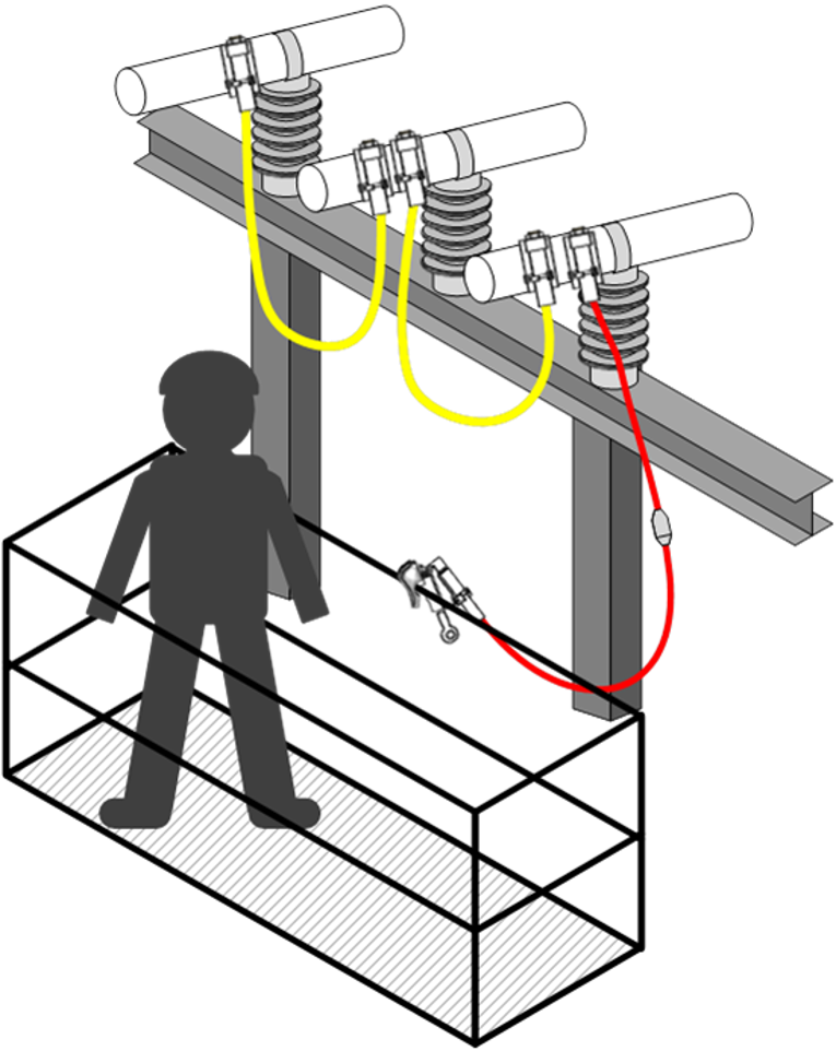
Uninsulated Basket Bonding
When it comes to using transmission line trucks not all of the elevated work platform baskets are insulated. It is essential that workers establish this prior to work as there are critical safety measures that must be applied if baskets are uninsulated.
When working within an uninsulated basket workers must use they type of bonding device shown in the image (red bond), which includes a safety decoupler. If in doubt about the appropriateness of equipotential bonding equipment please get in touch and we will put you in touch with an independent safety advisor who can clarify its suitability.
The purpose of bonding arrangements is to create an equipotentialised zone (EPZ), which is vital for the safety of those within the basket, and also to create a safe aerial rescue method.
If you would like to learn more about electrical health and safety issues relating to overhead line work, or permanent earthing / grounding for transmission infrastructure then please get in touch.